A Comprehensive Guide Of ISUZU Concrete Mixer Truck Components

Introduction to ISUZU concrete mixer truck

With the rapid development of domestic infrastructure projects, concrete has become the backbone of modern construction. The efficient transportation of ready-mixed concrete relies heavily on professional concrete mixer trucks, which are an important link between mixing plants and construction sites. These advanced vehicles combine automotive mobility with precise mixing technology to ensure that concrete maintains optimal consistency during transportation.


The core components of a ISUZU concrete mixer truck

1. Truck mixer chassis: the foundation

Function: Serves as the structural foundation and mobile platform

Features:

- Heavy-duty frame designed specifically by vehicle manufacturers

- Designed to support vehicle weight and concrete payload

- Equipped with reinforced suspension for increased carrying capacity

Importance: Determines the truck's carrying capacity and road performance

 ISUZU concrete mixer truck

2. Power Take-off (PTO) system

How it works:

- Extracts engine power without affecting vehicle operation

- Transmits power through couplings to drive hydraulic pumps

Main functions:

- Rotates the mixing drum

- Provides power for all mixing operations (charging, mixing, unloading)

Technical advantages: Maintains full functionality of the vehicle while operating the mixing system

 Concrete mixer truck

3. Mixing drum: the heart of the system

Structural design:

- Unique double cone shape with a cylindrical center

- Made of high-grade wear-resistant steel

- Dual continuous helical blades for optimal performance mixing

Innovative features:

- Secondary mixing blades between the main helices for enhanced homogenization

- Precision welded raceways for smooth rotation

- Reinforced rear cone with annular support ring

Capacity options: Available in single or double cone configurations depending on capacity requirements

 GIGA Concrete mixer truck

4. Material handling system

Loading components:

- Specially designed wide-opening feed hopper

- Reinforced chute system for precise material guidance

Discharging mechanism:

- Adjustable sliding discharge chute

- Hydraulic lifting system for optimal positioning

- Quick release mechanism for easy cleaning

Positioning: Strategically mounted at the rear for efficient field operation

 ISUZU Heavy duty Mixer truck

5. Support frame system

Structural integration:

- Heavy-duty subframe structure

- U-bolt mounting system for secure chassis connection

Vibration control:

- Special rubber shock-absorbing strips

- Designed to absorb operational stresses

Load management: Evenly distributes the weight of concrete on the chassis

 Concrete transport vehicle

6. Rotary drive system

Power transmission:

- Heavy-duty gear reducer

- Precision-engineered gear transmission with stable torque

Performance features:

- Variable speed control function

- Overload protection mechanism

- Sealed lubrication system for durability


The modern concrete mixer truck embodies the perfect combination of mechanical engineering and practical functionality. Its carefully engineered components work together to:

- Maintain concrete quality during transport

- Ensure reliable operation in demanding conditions

- Efficiently move materials on the job site

- Extend service life through rugged construction


Understanding this advanced system architecture helps operators maximize performance while enabling maintenance teams to properly care for these important construction vehicles. As infrastructure demands grow, continued advancements in mixer truck technology will further improve their efficiency and reliability on the job site.

Do you need more details on any specific subsystem or operating considerations? Please check below website:

https://www.isuzuvehiclescl.com/isuzu-concrete-mixer-truck

Composition and Working Principle of ISUZU Concrete Mixer Truck

ISUZU Concrete mixer trucks, commonly known as "cement mixer trucks", are essential vehicles for efficient transportation and mixing of concrete in construction. They consist of a special chassis with integrated rotating drum and hydraulic mixing system. This article will explore the key components and working principles of these vehicles.

ISUZU concrete mixer truck

A. Main components of concrete mixer trucks

1.1 Chassis and power system

- Most Chinese-made mixer trucks use a standard Class II commercial truck chassis.

- Power comes from the vehicle engine, which drives the hydraulic pump through the power take-off (PTO) system.


1.2 Power take-off (PTO) device

- Transmits engine power to the hydraulic system.

- Engage/disengage mixing operation through the control switch.

- Ensure that the drum rotates forward for mixing and reverses for unloading.


1.3 Hydraulic system

- Converts mechanical energy from the PTO into hydraulic energy.

- The variable pump drives the hydraulic motor, which in turn drives the mixing drum to rotate.

ISUZU GIGA Concrete Mixer truck

1.4 Speed Reducer (Gearbox)

- Reduces high-speed motor output to optimum drum speed (typically 2-6 RPM).

- Ensures smooth, controlled mixing.


1.5 Mixer Drum

- Made of high-strength, wear-resistant steel.

- Contains spiral blades inside for:

- Mixing concrete by lifting and tumbling the material.

- Efficient unloading when reversing.

- Drum capacity typically ranges from 3 m³ to 12 m³, depending on truck size.


1.6 Operating Mechanism

- Controls:

- Direction of rotation (forward for mixing, reverse for unloading).

- Speed (adjustable for different mixing stages).


1.7 Cleaning System

- Flushes residual concrete to prevent hardening.

- Cools the hydraulic system during operation.

- Some models include a drying function for special materials.

ISUZU GIGA concrete truck

B. Working Principle

2.1 Power Transmission

The truck engine drives the Power Take-Off (PTO), which in turn activates the hydraulic pump.

The hydraulic pump delivers high-pressure oil to the hydraulic motor, which converts hydraulic energy into mechanical rotation.


2.2 Mixing process

The mixing drum rotates clockwise (forward) during transport, keeping the concrete moving and preventing settling.

The spiral blades lift and tumble the mix to keep it at a uniform consistency.


2.3 Discharging process

The mixing drum rotates counterclockwise (reverse), pushing the concrete outward through the blades.

Control the discharge speed to ensure accurate positioning.


2.4 Cleaning and maintenance

After discharging, the mixing drum needs to be flushed to prevent concrete buildup.

Cool the hydraulic system to maintain efficiency.


2.5 Key considerations for optimal performance

- Blade integrity: Worn or damaged blades can cause uneven mixing and material segregation.

- Hydraulic system maintenance: Regular inspections prevent leaks and ensure smooth rotation of the mixing drum.

- Load capacity: Overloading can cause inefficient mixing and mechanical stress.

- Speed control: Proper adjustment prevents concrete separation or spillage.

ISUZU mixer truck

Concrete mixer trucks combine mechanical, hydraulic and structural engineering to efficiently deliver ready-mixed concrete. Understanding their components and working principles ensures their proper functioning, maintenance and longevity. Whether for small (3-6 cubic meters) or large (9-12 cubic meters) loads, these machines are indispensable in modern construction.

How to Choose A Refrigerated Truck That Fits Your Needs

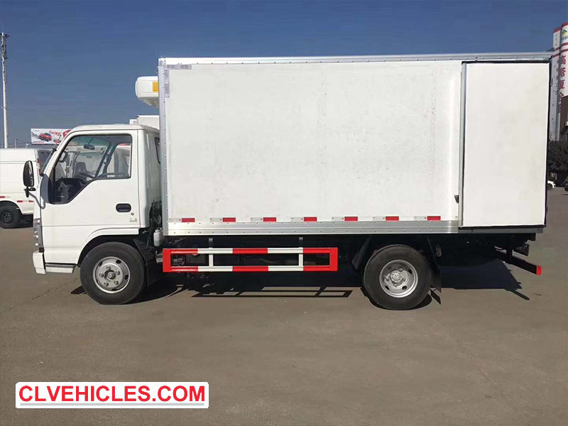
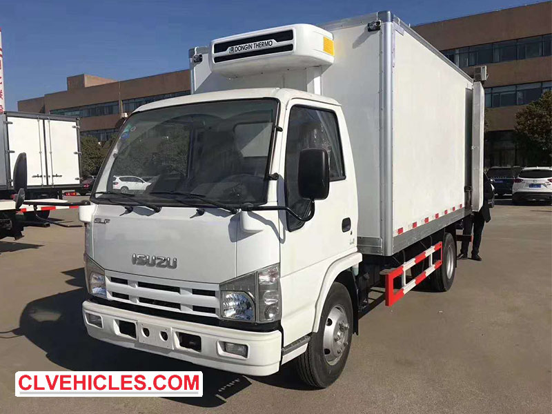
With rising temperatures and the rapid development of cold chain logistics, refrigerated trucks are becoming increasingly important in today's market. Choosing the right refrigerated truck requires careful consideration of three core components: chassis, refrigerated compartment and refrigeration unit, each of which is critical to ensuring the vehicle performs optimally for your specific transportation needs.

Refrigerated truck

Chassis selection: the foundation of refrigerated trucks

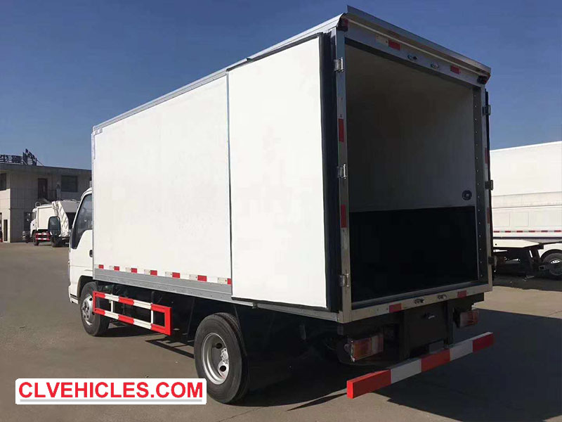
The chassis is the backbone of refrigerated trucks, and its selection is mainly based on cargo capacity and transportation distance. Light truck chassis are ideal for short-distance transportation, while heavy-duty chassis or semi-trailers are more suitable for medium- and long-distance transportation with heavier loads. Buyers are faced with the choice of sourcing the chassis themselves or entrusting the refrigerated truck manufacturer to purchase it. Contrary to popular belief, manufacturers often obtain better prices by establishing good cooperative relationships with chassis suppliers, while also ensuring the best modification compatibility. This professional approach usually provides a more suitable and economical chassis solution for refrigerated truck production. Here we recommend the chassis of ISUZU.

ISUZU Refrigerated truck

Refrigerated compartment: Tailored to your cargo needs

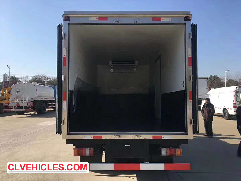
Refrigerated compartments need to be carefully configured according to the specific cargo characteristics. Special modifications include stainless steel meat hooks for transporting fresh meat, ventilated floor walkways for long and thin items, or multi-functional designs for frequent loading and unloading operations. While some consider converting standard cargo containers into refrigerated units to save costs, this approach has proven to be undesirable. Standard containers are usually made of iron or steel, have poor insulation and are prone to rust, making them fundamentally unsuitable for reliable cold chain applications. Specialized refrigerated compartments use appropriate insulation materials and structural designs to maintain constant temperatures and prevent contamination.

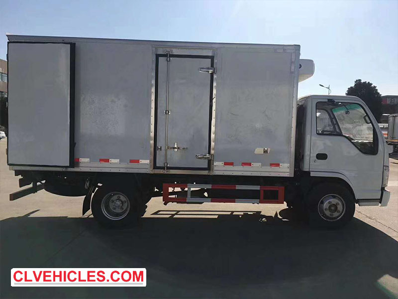
ISUZU ELF Refrigerator truck

Refrigeration Units: The Heart of Temperature Control

Selecting the right refrigeration unit requires consideration of three key factors: power configuration, temperature range, and manufacturing location. Dependent units are economical and suitable for short-distance delivery (within 7 meters), powered by the vehicle engine, but lack performance stability. Self-contained units are equipped with dedicated engines and generators to provide reliable cooling and are not affected by vehicle operation, which is critical for long-distance transportation of more than 7 meters. Temperature requirements determine the choice between deep freeze units (lower temperature, higher cost) and fresh-keeping units (moderate cooling, economical), while budget and performance expectations determine whether to choose imported units (excellent performance) or domestic units (economical). Imported units are particularly good at precise temperature control, especially for demanding applications such as semi-trailer refrigerated transportation.

ISUZU N series Refrigerator truck

By carefully evaluating these three basic components based on your specific transportation needs, cargo characteristics and operating budget, you can choose a refrigerated truck solution that provides reliable performance, optimal efficiency and long-term value in today's competitive cold chain logistics environment. Know more about our ISUZU Refrigerated Truck from https://www.isuzuvehiclescl.com/.


Installation and Use of Winch on ISUZU Wrecker Truck

Hydraulic winches are an essential part of an ISUZU wrecker trucks, providing critical lifting and pulling capabilities. These winches come in a variety of specifications, from light to heavy duty, and are an indispensable component in wrecker truck operations.

ISUZU ELF Wrecker Truck

The two most common types are worm gear hydraulic winches and planetary gear hydraulic winches, each of which has its own unique advantages:

Worm gear winches: simple design, cost-effective, easy to manufacture, often used in light to medium-duty applications (such as MLJ type hydraulic winches). However, their transmission efficiency is relatively low.

Planetary gear winches: more complex structure, this type of winch has higher torque, larger transmission ratio, and higher efficiency, making it an ideal choice for medium to heavy-duty operations.

ISUZU Flatbed Wrecker Truck

Installation of wrecker winches

Wreckers are usually equipped with one or two winches, which can be centrally mounted or offset mounted depending on design requirements. Proper installation and wire rope management are essential to ensure safe and efficient operation. Here are the key guidelines:

Double Deck Wrecker Truck

Pre-installation inspection

1. Check the components: Before installation, make sure all components are intact. Replace any defective components immediately.

2. Secure installation: Use high-strength bolts of grade 10.9 or higher to secure the winch to the base or bracket to ensure a secure mechanical connection.

3. Verify hydraulic connection: After installation, confirm that the hydraulic lines are connected correctly, the clutch engages/disengages smoothly, and the drum rotates smoothly.

ISUZU Flatbed Wrecker

Wire rope installation and calibration

Rope anchoring: Insert the end of the rope into the anchor hole of the drum and tighten it with a screw.

Pretensioning: Under no-load conditions, wrap 4-5 rope loops around the drum and then apply 3-5 kN of tension to ensure proper installation.

Calibration: The rope must be fed into the drum at an angle of no more than 3° to prevent misalignment and uneven force.

Anti-slip measures: When the winch is idling, be sure to enable the rope pressure device to prevent the rope from loosening or winding.

ISUZU ELF Wrecker Truck

Operational safety and maintenance

Run-in period: Before heavy-load use, the winch should be run without load to allow the hydraulic motor to run-in.

Load Limits: Never exceed the rated capacity of the winch - overloading can cause mechanical failure and accidents.

Clutch Safety: Do not disengage the clutch during lifting or pulling. Ensure that at least 5 rope loops remain on the drum during operation.

Proper installation, calibration, and maintenance of hydraulic winches are critical to the performance and safety of the tow truck. Following these guidelines ensures reliable operation, extends the life of the equipment, and minimizes risks during rescue missions.


Introduction of Four Main Parts of ISUZU Garbage Compactor Truck

ISUZU Garbage Compactor Truck compactors are essential garbage transfer vehicles in urban environments, with high transportation efficiency and safe and convenient operation. The upper body of this type of special vehicle consists of four key structural components: garbage bin, bucket assembly, barrel mechanism and hydraulic system, which all play a vital role in the garbage compression and transportation process.

Compact garbage truck

1. Garbage bin structure

The garbage bin is the main load-bearing unit. The large compactor is made of durable 16Mn steel plate (8mm, 5mm and 4mm thickness respectively) and reinforced with 16-gauge low-alloy channel steel; the standard model uses 12-gauge low-alloy channel steel with 5mm/4mm steel plates. This optimized steel frame combines lightness and structural integrity, maximizing internal capacity while lowering the center of gravity. The bottom channel steel is both the connection base of the structural components and the support platform of the push plate mechanism. The fully sealed bottom design effectively guides corrosive liquids and working water to the dedicated sewage tank, preventing container/chassis corrosion and roadside leakage during transportation. The entire assembly is firmly mounted on the truck chassis through a reinforcing beam connection.

Compress garbage trucks

2. Bucket assembly (waste loader)

The bucket system, as the main loading mechanism, integrates several coordinated components: a rigid frame skeleton with guide rails, a curved bucket, a scraping element, and a special slide equipped with eight high-strength, low-friction rollers on each side. These rollers enable smooth micro-vibration, which significantly reduces guide rail wear during long-term operation. The assembly contains a negative pressure plate and a lightweight cover layer to improve operating efficiency. At its bottom, a special sewage collection box automatically collects liquid waste during compaction and can be drained fully automatically or manually during unloading. This comprehensive design ensures reliable waste intake while maintaining clean operation.

Compressed garbage truck

3. Bucket flip mechanism

Commonly known as the flip mechanism, this component offers three configurable options to adapt to different municipal waste bins: a standard bucket mechanism (suspended bucket device), a flip mechanism customized to a specific waste bin design, or a roll-over system. This versatile subsystem is activated during vehicle travel to secure the waste bin and automatically retracts when not in use to maintain standard travel clearance. The mechanism’s intelligent design allows for seamless transitions between waste collection and road transport modes, with special attention paid to synchronization with vehicle movement to ensure operational safety and efficiency.

Compactor garbage truck

4. Hydraulic Power System

The hydraulic system is at the heart of the compaction truck’s operation and includes a large-capacity fuel tank, multi-stage filtration system, gear-driven oil pump, precision multi-channel control valves, check valves, heavy-duty cylinders, and an enhanced pipe network. Power comes from the truck’s main engine and is transmitted through a power take-off (PTO) that drives a hydraulic gear pump. This carefully designed system delivers the powerful power required for waste compaction and mechanical component operation while maintaining energy efficiency. The integration of specialized valves and controls allows for precise management of compaction cycles and component movement, ensuring optimal performance during demanding collection routes.

ISUZU GIGA Garbage truck

These four integrated systems work together to provide municipalities with an efficient waste management solution that combines rugged construction and practicality. From the corrosion-resistant waste bin to the wear-minimized bucket assembly to the powerful and precise hydraulic system, each component has been carefully designed to balance performance requirements with long-term durability. This comprehensive approach enables refuse collection vehicles to meet the demanding requirements of an urban environment while maintaining high operational efficiency and reliability.

ISUZU waste garbage truck

To know more about our ISUZU Garbage Compactor Truck, please check below website:

https://www.isuzuvehiclescl.com/isuzu-garbage-truck

ISUZU Road Sweeper Truck Introduction

Advanced Street Cleaning Solutions

Isuzuvehiclescl.com proudly introduces our self-developed ISUZU road sweeper truck, an advanced cleaning system designed for municipal and industrial applications. Based on the sturdy ISUZU F-Series chassis, this comprehensive cleaning system integrates multiple advanced technologies to provide excellent street maintenance performance.


Core System Components

1. Power System Configuration

Main Chassis: ISUZU F- Series

Auxiliary Power Unit:

- Cummins 4-cylinder turbocharged diesel engine

- 170 hp output

- Fan and water pump system dual-function drive

2. High-Efficiency Cleaning System

Air Filtration System:

- 8.0 High-Pressure Centrifugal Fan

- Maximum Air Volume: 23,500 m³/h

- Optimized for Dust Control and Debris Collection

Water Pressure System:

- PF36 Plunger High-Pressure Pump

- Working Pressure Up to 10MPa (1,450 psi)

- Precise Flow Control for Best Cleaning Effect

ISUZU Road sweeper truck

Innovative Storage Solutions

1. Water Management

Large-Capacity Water Tank:

- 9m³ Volume

- Space Optimized Design

- Integrated filtration system

2. Waste collection

Stainless steel trash can:

- 304 grade corrosion-resistant structure

- Hydraulic dumping mechanism

- High-pressure nozzle self-cleaning system

- Automatic removal of residues when unloading

ISUZU F-series Road sweeper truck

Precision cleaning technology

1. Brush system

Independent broom control:

- Optional left and right operation

- Multiple working modes (single side/full sweep)

- Wear-resistant bristle material

Performance advantages:

- Reduced sweeping times

- Reduced operating costs

- Extended service life

2. Advanced nozzle system

Wide range collection:

- 2,418 mm suction port

- Total working width of more than 3.5 meters

Adjustable components:

- 4 height-adjustable nozzle wheels

- Optimal ground clearance maintenance

Integrated water spray system:

- Fixed water spray bar

- High-pressure cleaning nozzle

- Design to minimize secondary pollution

Road Sweeper Truck

Intelligent control system

1. Hydraulic operation

Multi-function control:

- Broom lift/rotate

- Nozzle height adjustment

- Trash can door operation

- Trash can tipping mechanism

Open system design, higher reliability

2. Electronic management

One-touch operation:

- Simplified start/stop control

- System status monitoring

Low-pressure flushing:

- PTO driven water pump

- Integrated with chassis transmission

Road Washer Truck

Performance advantages

1. Improved cleaning efficiency

- Combination of mechanical and hydraulic sweeping

- Large-capacity suction system

- Precise water spray control

2. Economic operation

- Reduced water consumption

- Reduced maintenance requirements

- Extended component life

3. Environmental protection

- Effective dust suppression

- Minimize water waste

- Meet clean emission standards

4. Easy to operate

- Ergonomic control interface

- Automation function

- Easy maintenance access

ISUZU FTR Road Sweeper Truck

This comprehensive road cleaning system represents the latest advancement in municipal maintenance equipment, combining powerful performance with intelligent design to achieve superior cleaning results in urban environments. The integration of multiple cleaning technologies ensures optimal performance in a variety of road conditions and debris types.


Maintenance Guide for Six Major Systems of ISUZU Garbage Trucks

Proper maintenance of ISUZU garbage trucks is essential to ensure operating efficiency, extend service life, and avoid costly breakdowns. This guide details the maintenance requirements for the six key systems of garbage trucks.


1. Cooling System Maintenance

Service Interval: Every 6-8 months, or immediately if overheating/leaking occurs

Main Maintenance Tasks:

- Flush and replace coolant to prevent corrosion

- Check radiator, hoses and water pump for leaks

- Check thermostat operation and fan belt tension

- Clean radiator fins of debris and dirt accumulation

Warning Signs:

- High engine temperature gauge reading

- Visible coolant leak under the vehicle

- Discolored or contaminated coolant

ISUZU compactor garbage truck

2. Transmission System Maintenance

Service Interval: Every 800-1,000 km or when symptoms occur

Basic Procedure:

- Drain and replace transmission oil

- Clean transmission oil pan and replace filter

- Check seals and gaskets for leaks

- Check shift linkage for proper adjustment

Troubleshooting Indicators:

- Slipping during acceleration

- Delayed or rough shifting

- Transmission oil leaking

- Abnormal whining or grinding noise

ISUZU 5CBM garbage truck

3. Brake system inspection

Maintenance interval: every 800 km

Key maintenance:

- Flush and replace brake fluid

- Check brake pads/shoes and rotors/drums

- Check brake lines for leaks or damage

- Test parking brake function

- Lubricate caliper slide pins

Safety warning signs:

- Brake pedal is too soft or spongy

- Vehicle pulls to one side when braking

- Grinding or squealing noise

- Brake warning light comes on

ISUZU 8CBM compactor garbage truck

4. Lubrication system maintenance

Maintenance interval: every 5,000-10,000 km or when a problem occurs

Maintenance requirements:

- Replace engine oil and oil filter

- Clean oil pan and filter

- Check for oil leaks

- Check oil pressure

Performance indicators:

- Increased engine noise

- Reduced power output

- Increased operating temperature

- Oil pressure warning light comes on

ISUZU ELF compactor garbage truck

5. Fuel system cleaning

Maintenance interval: 800-1,000 km

Maintenance procedures:

- Replace fuel filter

- Clean fuel injectors

- Check fuel lines and connections

- Check fuel pump operation

- Remove carbon deposits from combustion chambers

Symptoms to watch out for:

- Rough idle or engine vibration

- Poor acceleration

- Reduced fuel efficiency

- Difficult starting

ISUZU 15CBM compactor garbage truck

6. Power steering system

Maintenance interval: 1,000-2,000 km

Maintenance checklist:

- Flush and replace power steering fluid

- Check hoses and connections for leaks

- Check condition of steering gear and pump

- Lubricate steering linkage

Problem indicators:

- Steering fluid leaks

- Whining noise when steering

- Stiff or unresponsive steering

- Foaming or discolored steering fluid

ISUZU 6CBM garbage truck

By following this comprehensive maintenance plan, you can ensure your junk truck is running at peak performance while minimizing unexpected repairs and downtime. Always consult your vehicle's specific maintenance manual for the manufacturer's recommended procedures and intervals.

Pre-Operational Safety Checklist for ISUZU Aerial Work Platform Trucks

ISUZU Aerial Work Platform Truck are essential tools for temporary mobility during maintenance, construction and emergency operations. Unlike permanent structures such as elevators, these vehicles require strict safety procedures before operation to prevent accidents. Below is a comprehensive pre-operation checklist to ensure safe and efficient use.

45m ISUZU manlift truck

1. Pre-Operation Inspection

Before driving or operating an AWP, perform the following inspections:

A. General Vehicle Inspection

Oil Levels: Check engine oil, coolant and hydraulic oil levels.

Power: Check battery charge and electrical connections.

Tire Pressure: Ensure tires are adequately inflated and free of damage.

B. Stability and Setup

Ground Conditions: Operate only on flat, stable surfaces - soft or uneven ground may cause tipping.

Outrigger Deployment: Extend and lock all four stabilizing outriggers to ensure full load support and levelness.

C. Hydraulic System Inspection

- Verify hydraulic oil is at recommended level and check for leaks.

D. Boom and Jib Inspection

- Ensure all boom sections are fully retracted and securely locked.

- Check for loose bolts, worn cables, or damaged hydraulic hoses.

ISUZU aerial working truck

2. Job Site Hazard Assessment

Before raising the platform, assess the working environment for potential hazards:

A. Ground Hazards

- Steep slopes, ditches, or unstable ground.

- Protrusions, debris, or obstructions that could affect stability.

B. Overhead and Electrical Hazards

- Power lines, tree branches, or other overhead obstructions.

- Stay at least 10 feet (about 3 meters) away from high-voltage power lines.

C. Environmental Conditions

Wind Speed: Do not operate if wind speed exceeds 12.5 m/s (28 mph).

- Rain, snow, or ice can make the ground slippery—avoid use in inclement weather.

D. Unauthorized Access

- Access restricted to trained personnel only—no entry for unauthorized personnel.

ISUZU aerial platform truck

3. KEY SAFETY PRECAUTIONS DURING OPERATION

A. Tipping Hazard

Do not exceed the maximum platform weight (check manufacturer's weight limits).

Do not extend the boom unless the vehicle is on firm, level ground.

Avoid sudden movements - operate controls smoothly.

B. Fall Prevention

Wear a full body harness and secure it to designated anchor points.

Stand on the platform floor - do not climb on guardrails.

Keep platform free of tools and debris to prevent tripping.

Before lifting, make sure access gates are closed.

C. Collision Risk

Continuously check for obstructions in the boom's path of movement.

When adjusting guardrails, do not place hands in pinch points.

Lower the boom only when the area below is clear.

D. Fire and Explosion Prevention

Do not start the engine if a fuel leak or odor is detected.

Refuel only in a well-ventilated area and away from sources of ignition.

Do not refuel or charge near open flames or sparks.

ISUZU manlift working truck

Conclusion

Safe operation of aerial work platforms requires a thorough pre-use inspection, hazard awareness, and strict adherence to safety procedures. By following this checklist, operators can minimize risk, prevent accidents, and ensure efficient operation.

Remember: a 10-minute inspection can save a lifetime of regret. Play it safe and operate responsibly!


Benefits and Necessity of Upgrading to Aluminum Intake Manifolds

In recent years, the automotive world has witnessed a growing trend among car owners and enthusiasts: the modification of intake manifolds. This once-overlooked component is now at the forefront of performance upgrades, driven by advancements in materials, engineering, and a relentless pursuit of enhanced driving experiences. But what exactly is fueling this surge in popularity? Let's dive into the reasons why more and more people are turning to intake manifold modifications.


Aluminum intake manifold

The increasing popularity of intake manifold modifications can be attributed to several key factors:


1. Performance Enhancement

Improved Airflow Efficiency:Upgrading to a high-performance intake manifold, such as one made from aluminum or composite materials, can significantly reduce air resistance and improve airflow into the engine.


Better Engine Response:Aluminum intake manifolds are lighter than their cast iron counterparts, which improves the engine's dynamic response and overall performance.


2. Weight Reduction

Lightweight Materials:Modern aluminum and composite materials used in aftermarket intake manifolds are significantly lighter than traditional cast iron or even some cast aluminum components.


3. Enhanced Thermal Management

Lower Intake Air Temperature: Aluminum and certain composite materials have better thermal conductivity and lower heat retention compared to cast iron.


4. Customization and Compatibility

Tailored Designs: Aftermarket intake manifolds can be customized to match specific engine configurations and performance goals. For example, some designs offer adjustable runner lengths to optimize performance across different driving conditions


Aluminum intake manifold


5. Aesthetic Appeal

Enhanced Engine Bay Appearance:Many aftermarket intake manifolds are designed with aesthetics in mind, featuring polished aluminum surfaces or other visually appealing materials


Aluminum intake manifold

Jagrow BMW G8X Metal Skid Plate Undertray (Oil Cooler Guard)

Jagrow BMW G8X Metal Skid Plate Undertray (Oil Cooler Guard) – Ultimate Defense for Your S58 Engine


The OEM Vulnerability

The factory plastic oil cooler guard on your BMW G80 M3 / G82 M4 / G87 M2 is a critical weak point: BMW G8X Metal Skid Plate


Scrapes from speed bumps or steep driveways BMW G8X Metal Skid Plate


Debris impacts during spirited driving or track days

· 

Heat-induced brittleness leading to catastrophic cracking
A single failure can send plastic shards into your $2,000+ oil cooler, risking catastrophic engine failure.


Jagrow’s 3mm Aluminum Solution
Precision-engineered from aerospace-grade 6061-T6 aluminum:
✅ Military-Grade Protection – 50kg vertical impact tested, 300% stronger against road debris
✅ Feather-Light – Only 0.8kg added weight (0.3kg over OEM plastic)
✅ Corrosion-Resistant – German powder coating in Race Red, Stealth Black, or custom colors
✅ Bolt-On Fitment – Uses OEM mounting points, installs in 30 minutes


Customization Options

Laser Engraving: Logos, owner signatures, or track numbers

· BMW G8X Metal Skid Plate


OEM/ODM Services: Bespoke colorways and branding for tuners

 BMW G8X Metal Skid Plate

Limited Editions: Launching "Track Attack Red" and "Carbon Fiber Black" finishes

 BMW G8X Metal Skid Plate

Act Now
Visit https://www.alibaba.com/x/4weId?ck=pdp for custom quotes.

Protect Your M Power. Choose Jagrow.
Support Jagrow – Fueling innovation in automotive protection.